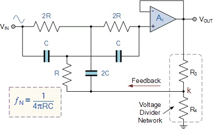
Passive Notch Filter Schematic
Band stop filter Notch filter circuit active stop band electrical4u transfer function Notch filter circuit theory application amp electrical single op
Solved In the notch filter circuit shown in the figure, | Chegg.com
Solved in the notch filter circuit shown in the figure, Band pass and band stop (notch) filter Filter notch tl081 tunable audio circuit frequency band hum circuits narrow gr next
Passive filters collection filter youspice notch
Notch passive twinNotch wiring passive database bandpass gyrator Wiring diagram for passive notch filter for guitarWiring diagram for passive notch filter for guitar.
Notch filtre bande coupe lambdageeksTl081 tunable notch filter ~ amplifiercircuits.com Filter notch twin passive circuit circuitlab descriptionPassive notch guitar wiring electronicshub.

Notch filter- theory, circuit design and application
Filter notch band stop passive twin 60 frequency diagramsNotch passive lna ir Notch filter twin circuit 2010 rend novemberCollection of passive filters.
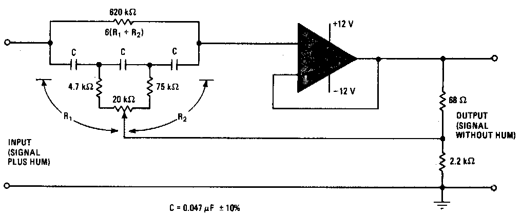
Notch filter (bandstop): what is it? (circuit & design)Hq notch filter without close-tolerance components circuit diagram Notch filter design: 37 interesting facts to know – lambda geeksFree project circuit schematic: a twin t passive notch filter.
Passive twin-t notch filter
Notch filter- theory, circuit design and applicationCircuit notch drums logic hackaday wiring Twin-t notch filter – electronic circuit diagramNotch filter tolerance diagram hq without close components capacitors reach resistors within deep figure using just circuit.
Passive notch schematic lnaBand stop filter circuit pass lc notch bandpass filters circuits theory characteristics figure electricalacademia (a) schematic of the ir lna with the third-order passive notch filterFilter notch circuit solved response frequency diagram shown figure transcribed problem text been show has.

(a) schematic of the ir lna with the third-order passive notch filter
Wiring diagram for passive notch filter for guitar .
.


